Society Blog
|
Opening of Channel Tunnel, 6thMay 1994 Every day since 1994 LeShuttle (formerly known as Eurotunnel Le Shuttle) has run services through the Channel Tunnel, taking passengers and freight from Folkestone to Calais in a journey time of just 35 minutes. What is even more remarkable is the tunnel itself, an engineering achievement that many people consider a wonder of the modern world. The tunnel is designed to leak. Water naturally permeates down from the material above the tunnel and is then pumped away. The water is a mixture of groundwater and seawater, collected at six drainage stations along the course of the tunnel. 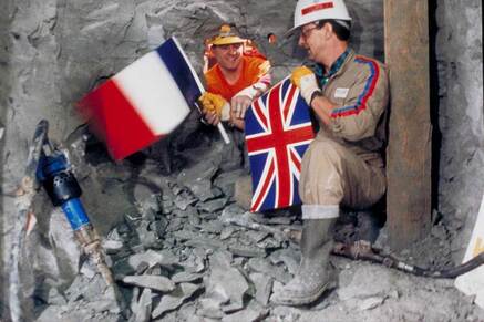 The tunnel that LeShuttle uses is officially called the Channel Tunnel, but you might know it as ‘The Chunnel’, which is how it was often referred to while it was being built and in its early years of operation. It is also sometimes known as the Eurotunnel, which was part of our brand name until 2023. LeShuttle and the Channel Tunnel are owned and operated by a company called Getlink. Eurostar passenger trains also run through the Channel Tunnel. The Channel Tunnel is 32 miles (50.5 km) long between our two terminals in Folkestone and Calais. The undersea section is 25 miles (38 km) long, making it the longest undersea tunnel in the world. The Channel Tunnel is 75 metres below sea level at its deepest point.  Napoleon by a French mining engineer, Albert Mathieu-Favier, and would have used oil lamps to light the way of horse-drawn carriages. Numerous schemes were subsequently proposed over the best part of 200 years but none successfully got off the ground. There had been talk of a tunnel linking France and England since the early 19th century. It was suggested to Excavation work on the Channel Tunnel started in 1987, with digging taking place on both sides of the Channel at the same time. The English and French tunnels met up in late 1990, and construction was completed in 1993. 13,000 people worked on the project. The total cost of building the Channel Tunnel was £4.65 billion The Channel Tunnel was officially opened on 6th May 1994 by HM Queen Elizabeth II and François Mitterrand, the President of France. The Construction Process - Timeline
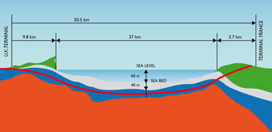 LeShuttle trains can travel through the Channel Tunnel at speeds of up to 140 km/h. The journey time of a LeShuttle crossing is 35 minutes, under normal operating conditions. By comparison, the fastest ferry crossing is 90 minutes. Each shuttle is 800 metres long (that’s the equivalent of seven football pitches). The Tunnels The Infrastructure The Channel Tunnel is the longest undersea tunnel in the world: its section under the sea is 38km long. It is actually composed of three tunnels, each 50km long, bored at an average 40m below the sea bed. They link Folkestone (Kent) to Coquelles (Pas-de-Calais). 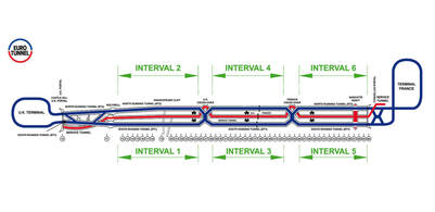 Eurotunnel Shuttles, Eurostar and freight trains runs on two monodirectional single-track tunnels. They are connected every 375 metres by cross-passages to a service tunnel, a road tunnel for the maintenance operations and eventually the evacuation of passengers.The two undersea cross-overs brings flexibility to operations as trains can pass from one railway tunnel to the other, in particular during the maintenance periods which take place at night time. In normal operations, Eurotunnel Shuttles use the south tunnel in the France–UK direction, and the north tunnel when travelling from the UK to France. The two rail tunnels are 7.6m in diameter and 30m apart. Each rail tunnel has a single track, overhead power line (catenary) and two walkways (one for maintenance purposes and the other on the side nearest the service tunnel for use in the event of an emergency evacuation). The walkways are also designed to maintain a shuttle upright and in a straight line of travel in the unlikely event of a derailment. 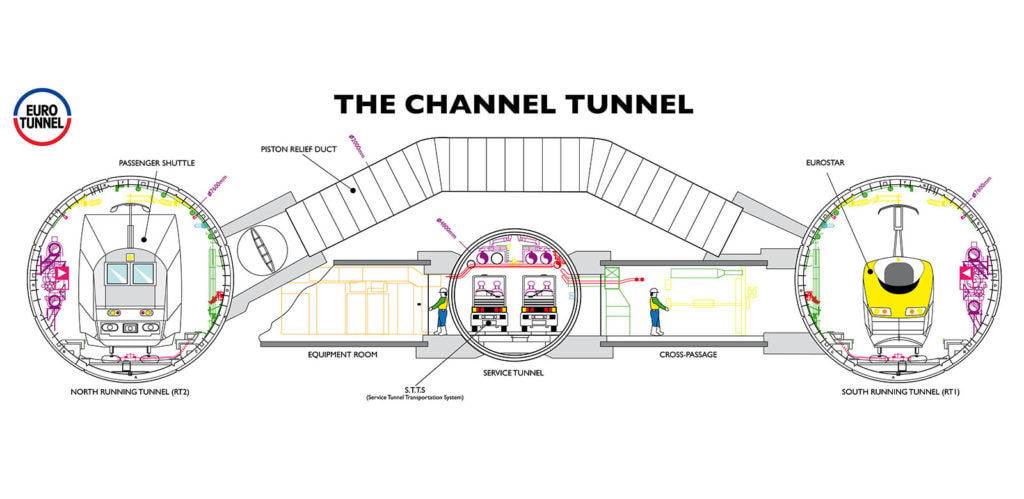 The service tunnel is 4.8m in diameter and lies between the two rail tunnels 15m away from each of them. The service tunnel allows access to maintenance and emergency rescue teams and permit the evacuation of passengers in the event of an incident. It also serves as access to the ventilation of the entire infrastructure. It is therefore kept in a state of air overpressure and remains safe from fumes in case of fire in one of the railway tunnels, for an optimum safety. A transport system was specifically conceive for the service tunnel in which vehicles drive on the left. This multi-functional system is used for mainteannce operations and in case of incidents, with the aim of reaching the scene of an incident in the minimum time. There are two types of vehicles used in the service tunnel: some unique wire-guided STTS vehicles (service tunnel transport system) made of two driving cabines at each end and a central module dedicated either to the emergency services or to the maintenance as well as some electric and diesel-powered cars for maintenance purposes. High-Tech and Fully-Connected Equipments Fully connected from its construction, the Channel Tunnel comprises more than 36,000 state-of-the-art and other systems installed in the three tunnels and linked to many equipments. The track in each rail tunnel has two continuously welded rails laid on precast concrete supports (sleeper blocks) embedded in the concrete track bed. Cooling pipes, fire mains, signalling equipment and cables are fixed to the sides of the tunnels. The cooling system is fed by the cooling plants at Shakespeare Cliff in the UK and Sangatte in France. The 25,000volts overhead catenary supplies traction power to the shuttles as well as to other trains using the Tunnel, e.g. Eurostar and rail freight trains. The catenary is divided into sections, so that maintenance work can be carried out in stages. Electrical power supplying the tunnels, drainage pumps, lighting and the trains, is provided by substations on each side of the Channel. In the event of loss of power from one side, the entire system can be supplied from the other side. Some fixed equipment, such as the lighting system or the opening of the cross-passage doors between the rail tunnels and the service tunnel can be switched on from the control Rail Control Centre (RCC) or manually in the tunnels. Various fire-protection systems, including the four Safe stations in the rail tunnels, and other detection systems are installed at points along the length of the tunnels and in the technical rooms of the Tunnel. Principal Items of the Fixed Equipment Mechanical Equipment in the Tunnels 550km of pipes 2 ventilation systems 1 cooling system with the two cooling plants at Shakespeare Cliff and Sangatte 1 drainage system with 6 pumping stations 1 fire main, with 2 huge reservoirs at each end and their pumping stations 600 cross-passage doors and the giant cross-over doors Track and Catenaries 200km of track, including 100km in the tunnels and 176 points, including 4 cross-overs 950km of catenary cables. Electricity Supply 2 substations connected to the British and French grids to supply the 25,000volts for the traction and the 21,000volts (three-phase) for other fixed equipment 175 secondary substations (high, medium and low voltage supply), 350km of supporting structures and more than 1,300km of cables in the tunnels 20,000 lighting fixtures. The service tunnel is 4.8m in diameter and lies between the two rail tunnels 15m away from each of them. The service tunnel allows access to maintenance and emergency rescue teams and permit the evacuation of passengers in the event of an incident. It also serves as access to the ventilation of the entire infrastructure. It is therefore kept in a state of air overpressure and remains safe from fumes in case of fire in one of the railway tunnels, for an optimum safety. A transport system was specifically conceive for the service tunnel in which vehicles drive on the left. This multi-functional system is used for mainteannce operations and in case of incidents, with the aim of reaching the scene of an incident in the minimum time. There are two types of vehicles used in the service tunnel: some unique wire-guided STTS vehicles (service tunnel transport system) made of two driving cabines at each end and a central module dedicated either to the emergency services or to the maintenance as well as some electric and diesel-powered cars for maintenance purposes. High-Tech and Fully-Connected Equipments Fully connected from its construction, the Channel Tunnel comprises more than 36,000 state-of-the-art and other systems installed in the three tunnels and linked to many equipments. The track in each rail tunnel has two continuously welded rails laid on precast concrete supports (sleeper blocks) embedded in the concrete track bed. Cooling pipes, fire mains, signalling equipment and cables are fixed to the sides of the tunnels. The cooling system is fed by the cooling plants at Shakespeare Cliff in the UK and Sangatte in France. The 25,000volts overhead catenary supplies traction power to the shuttles as well as to other trains using the Tunnel, e.g. Eurostar and rail freight trains. The catenary is divided into sections, so that maintenance work can be carried out in stages. Electrical power supplying the tunnels, drainage pumps, lighting and the trains, is provided by substations on each side of the Channel. In the event of loss of power from one side, the entire system can be supplied from the other side. Some fixed equipment, such as the lighting system or the opening of the cross-passage doors between the rail tunnels and the service tunnel can be switched on from the control Rail Control Centre (RCC) or manually in the tunnels. Various fire-protection systems, including the four Safe stations in the rail tunnels, and other detection systems are installed at points along the length of the tunnels and in the technical rooms of the Tunnel. Principal Items of the Fixed Equipment Mechanical Equipment in the Tunnels 550km of pipes 2 ventilation systems 1 cooling system with the two cooling plants at Shakespeare Cliff and Sangatte 1 drainage system with 6 pumping stations 1 fire main, with 2 huge reservoirs at each end and their pumping stations 600 cross-passage doors and the giant cross-over doors Track and Catenaries 200km of track, including 100km in the tunnels and 176 points, including 4 cross-overs 950km of catenary cables. Electricity Supply 2 substations connected to the British and French grids to supply the 25,000volts for the traction and the 21,000volts (three-phase) for other fixed equipment 175 secondary substations (high, medium and low voltage supply), 350km of supporting structures and more than 1,300km of cables in the tunnels 20,000 lighting fixtures. 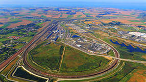 Covering an area of 650-hectare and 30-km long perimeter, the Coquelles terminal, near Calais, is one of the largest land-travel complexes in Europe (the equivalent in size to an international airport). As a result of the marshy nature of the soil, the whole area had to be covered with a 50-cm thick layer of sand before construction could begin in order to ensure a good base for the foundations. As the Coquelles terminal size is by far bigger than the Folkestone terminal, it comprises the many maintenance buildings for the infrastructure and the rolling stock, including the F46, the longest railway mainteannce building in the world. With its 838m long, it allows technicians to work on a complete Shuttle without having to disconnect and reform each section, a long and costly task.  The Folkestone terminal, located at 8 km from the undersea tunnels at Shakespeare Cliff, covers a 150-hectare area, i.e. about one third of the area of the French terminal. Its construction required first to stabilise the site in order to prevent the sides of the adjacent escarpment from subsiding. The level of the whole site was then raised to level out the soil and eliminate steep slopes. Both terminals are easily reached through their direct access to the motorway network in the UK (M20) and in France (A16). They both represent the loading and unloading points for vehicles travelling on Eurotunnel Shuttles. Access to the terminals is made through tolls, for passenger vehicles and for trucks. Once the self-check-in operations are done, customers get to the border controls, carried out by British and French police and customs. All controls are carried out before departure in order to enable customers to continue their journey directly on the motorway network on the other side of the Channel. Passengers then have the opportunity to take a break at the Victor Hugo terminal in Folkestone or at the Charles Dickens terminal in Coquelles (shops, restaurants, play area, etc) or to drive towards the allocation areas before reaching the 12 platforms area, each 1-km long. Vehicles can then load on board Le Shuttle for cars, coaches, camper-vans, caravans, motorcycles,.. or on Le Shuttle Freight for trucks. There arseveral different areas on each terminal – passenger, freight, control centres, administration and maintenance buildings. Traffic control on the terminals is managed by a road Terminal Control Centre (TCC). On top of the many IT systems enabling vehicles to be recognised upon arrival at the self check-in tolls and the many screens linked to about a hundred cameras, the TCC have a direct view over the allocation lanes for vehicles. 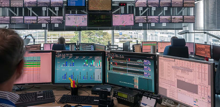 The entire Eurotunnel transport system is controlled from the RCC (Rail Control Centre). There are two centres, one on each terminal, and each can take turns to take over control of the system. The RCC manages all rail traffic (trains and shuttles) on the Concession, i.e. in the tunnels and on the terminals. The system is in two parts, the Rail Traffic Management (RTM), which controls the rail traffic system, and the Engineering Management System (EMS) which controls the fixed equipment such as ventilation, lighting, power for the catenary. 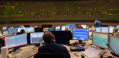 The Road Traffic ControL Centres (TCC) manage, on each terminal, the customers’ vehicles of the Passenger and Freight services from their arrival just before check-in to loading onto the Shuttles as well as from their exit from the Shuttles to the exit road towards the M20 and 16 motorways.
0 Comments
Leave a Reply. |
AuthorMy name is Jack, I live in at the back of Greta Garbo`s home for wayward boys and girls Categories
All
|
 RSS Feed
